|
50% of the problems are servo problems. Any
one can troubleshoot with basic knowledge.
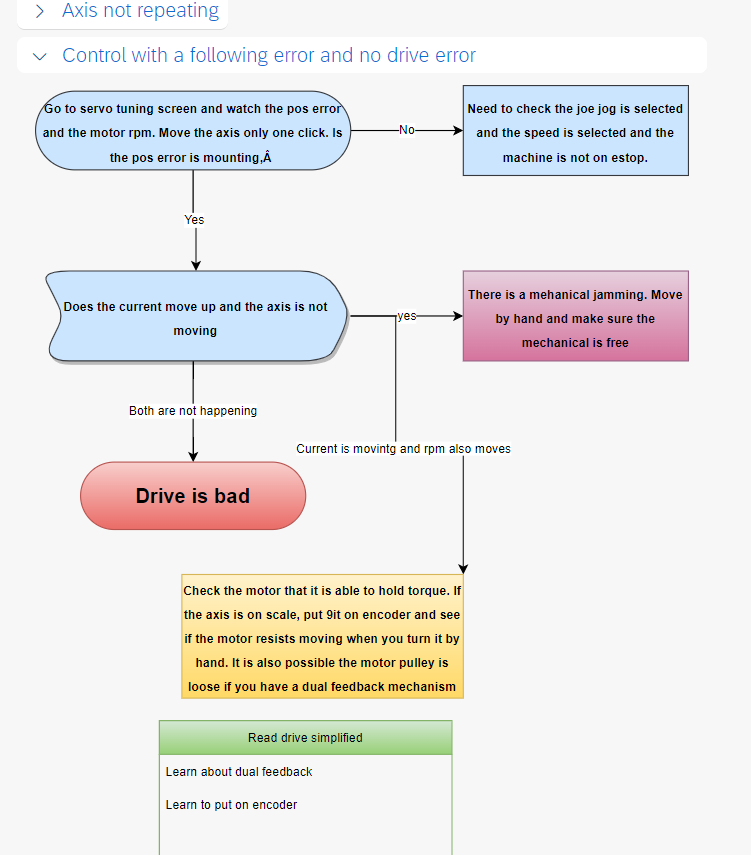
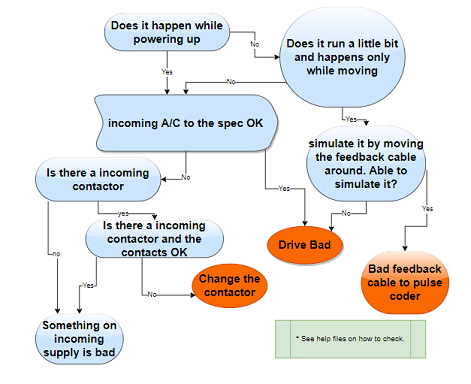
Flowchart with simple YES or NO questions.
Text and picture help to answer the
questions.
You can save 1000s. PERIOD. Premium members get email and phone
support for free.
FANUC
Drive troubleshooting and CNC
troubleshooting- Android-
Free Download
FANUC
Drive troubleshooting and CNC
troubleshooting - Apple IOS-
Free Download
How to select an Alarm and Symptom
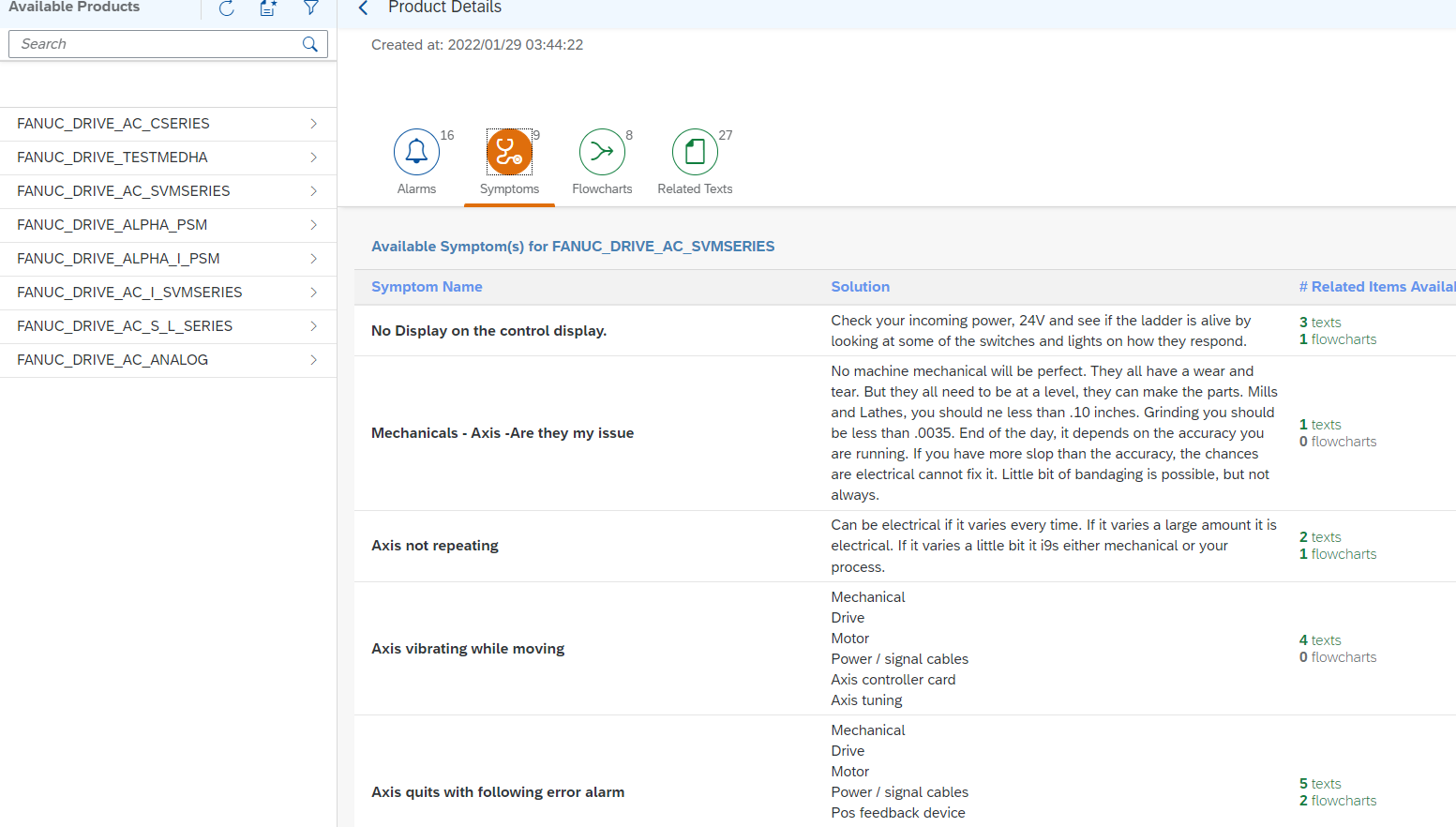
Description
This is the go to app to learn the
fundamentals of CNC Machines.
Do you know that
it costs an average of $5,000 for a service
engineer to walk into your facility? Using
this troubleshooting app you can learn how the
machine and its components work.
The Step by step
flowcharts included in these two apps will
walk you through to troubleshoot your
problem. All you have to do is answer YES or
NO. If you don’t know the answer, you have
help in the form text that can help you
answer the question. The idea is to narrow
it down to one or two faulty parts.
Sometimes buying two parts is cheaper and
faster than getting a CNC engineer to visit
your site.
We have alarm and
symptom approaches to troubleshooting.
How to
get more info on other products
Visit
www.drmachines.com to learn about
what is done so far and what else is on the
pipeline.
Collaboration and customization
Who
are we:
This
is a troubleshooting knowledgebase app is
brought to you by CNC Onestop, Inc. who are
experts on all kinds of CNC and PLC based
machines. We also sell parts and we have
special offers, free tech support and free
restocking privileges for those who buy
parts from us. We also give training to
people in your location or in our location.
History:
Our
Chief Engineer Ven Swaminathan has a Masters
degree in Electronics and has over 35 years
of 15 hour a day hands on service
experience. Even today he is much sought
after in almost all of the aircraft and
automotive companies in the US. He
personally has worked for 1200 companies in
North America. He is experience in more
than 100 type of controls and a few hundred
models of machines. His passion towards
bringing his knowledge to the machine tool
owners to do it themselves has evolved into
the tool called Share Your Expertise.
Plans: We
are launching the first version of this app
for free. We will be adding more makes and
models of drives, spindles and controls. We
also provide help through Apple FaceTime for
a fee. We also have support engineers who
can come to your place and troubleshoot your
machine. We are all about quality and
one-stop troubleshooting. There are no
machines we cannot fix. When we walk out we
will have your machines running. We provide
the parts you need and will be one-stop
solution for you. Either do it yourselves or
take our help to the extent you like. We
want to be the one-stop center for your CNC
needs.
Partners: We
are also looking for independent service
engineers all over North America. If you are
an independent service engineer and if you
have what it takes to troubleshoot any
machine send us your resume. If you meet
our expectations, you will have an
opportunity to represent us. Our engineers
work about 3000 hours and wait time is 3
weeks to get one. We have contract with
several OEMS to service their machines all
over North America. Our average is one out
of 50 people who apply qualify to work with
us. We are for quality than quantity. We
look for technical ability, attitude to
troubleshoot, maturity to deal with the
customer and above all a CAN DO attitude. If
you are the best in the business, email us.
Visit
www.drmachines.com to learn about
what is done so far and what else is on the
pipeline. If you need a portal for your
company and any more ideas you have on how
you can use the system inbternally.
SAMPLE OF KNOWLEDGEBASE FROM THE APP
Knowledgebase on CNC
4. Different parts of a CNC Control
4.1
Numerical control:
Photocell was used to
detect the holes punched in a paper tape. NC
control used this information and sent a
command to the servo drives to make the
move. This is how simple the NC machine was
in the earlier stages of 1960s.
4.2
CNC Control:
After the development
of computers, which comprised of memory,
input/output mechanism, display unit and a
keyboard, it was possible to create, edit
and delete a program with ease. Combining
the computers to NC machines made it a CNC
machine. The following topics will deal with
different components of a CNC machine.
4.3 Power supply is
the heart of a machine. Without a power
supply nothing will work. A power supply
gives out DC voltages for ac input. There
are different kinds of power supplies. The
common one is Linear.
4.3.1 Linear Power supply:
This is a basic power supply. For an ac
input it gives out specified dc output. Even
without a load it will put out an output. It
regulates the output voltage up to a
designed load. Some power supplies will blow
a fuse if it is overloaded and some will go
into a fold back mode putting no output but
still saving the power supply. The
efficiency is low. It is bulky. The main
characteristic in service point of view is,
it should put out a voltage with no load. It
can have several protective circuits.
4.3.2 Switching Power
supply (SMPS): Switching
mode power supplies are advanced power
supplies. The efficiency is high. With
higher loads it goes into protective mode.
This makes it more reliable and gives a
longer life span. It is also possible to
design for varied inputs like 100 to 240
volt input for the same output. It is
compact and can weigh very less. Most of the
laptops has this kind of power supplies.
It has to be tested with the
minimum specified load. Though some of them
will put out voltage without a load
connected to it, the earlier models will
need a load to be connected to it.
4.3.3 Checking of Power
Supply:
a) Machine may have more than one power
supply. One for the control, one or more for
drives one for spindle, one for external
source (Mostly 24V). First thing to find out
which power supply is being suspected.
b) Make sure the input ac is available
at the terminal of the power supply to the
specification. Always measure across the ac
terminal than going across terminal to
ground.
c) Check all the possible dc outputs.
Dc output should be 1.414 times the A/c
input. Be aware the PSU may have its own
transformer inside to supply different AC
inputs for several possible DC outputs.
d) Check the dc outputs with no load or
slight load
e) If there are some extra wires other
than input they could be acting as switch
from external sources. Make sure they are at
where they should be.
f) Remove all the loads and check for
resistance across the wires like 5V and 0,
12V and 0, 24V and 0. Make sure they are not
shorted, by measuring the resistance across
the load. If they have very low resistance
or short, then the problem is in the load
side and not in the power section.
g) Once it is decided, it is the power
supply, check for any blown fuses in Input
or Output side.
h) Remove all the wires and check for
the Input resistance on the power supply and
whether it is shorted.
i) Similar to the above check and
make sure the Output resistance of the power
supply is not shorted either.
j) If you suspect only one power
supply load side is shorted, Load Testing
can be done. Calculate the power output by
multiplying output voltage by rated current,
and find a bulb with lower than that
wattage. Connect it and see if it comes on.
A thing to remember is, if it is a switching
PS all the outputs should have a minimum
load.
k) Some power supplies might have a
terminal for Remote Sensing. This senses the
voltage at a remote place where the load is
and adjusts the power supply to put out a
voltage specified at the remote place. A 5V
PS can be 5.2 at the output terminals, where
as it could only be 5V at the remote place.
l) Some power supplies may have a
capacitor externally connected. Make sure it
is OK.
4.4 Power Conductors:
The wires, which are carrying the power
supply to different section, have to tight with least amount of drop in the
wires as well as in the connectors. Otherwise will behave unpredictably.
4.5 Processor:
Processor is the brain of a CNC machine.
When this is dead it is like; the machine is in coma. It can not apply
logic. Normally the processor board can be one or more than one boards,
depending on when it was made. It takes the information from the memory,
processes it, and gives the appropriate command to the axis and spindle.
While doing so it takes input from the input board as to what is the status
of the machine like whether it is in home or not, has it been homed yet,
what is the position of the tool changer etc. Then it processes that
information through logic called "ladder" and decides whether it can ask the
Axis to move, so that it will be a safe movement. Also it gives output to
tool changer, pallet changer, based on the present status of the machine.
Usually processor boards will have some
light indicating that it is running or halted. This gives a good indication
about whether it is having a problem or running OK. Lot of machines have
motherboard which will have processor board built in with some other
features. It is always advisable to read the specific description about the
processor board. This information can be found in the control manual.
4.6 Memory: I t is same as in human memory. The commonly
used memories are RAM, EEROM/EPROM/Core memory and Hard disk/Bubble memory.
Core memory was used to store all the information. This kind is not being
used because of poor reliability and cost. Most of the recent machines use
EEROM/EPROM for storing the system information, RAM for parameters, and hard
disk for programs.
RAM - Read and write memory, fast access
time
ROM - Read Only memory
EEROM - Electrically erasable ROM
EPROM - Same as above, but can be erased
only under UV rays.
Hard disk/Bubble memory - Can be read and
wrote but not as fast as RAM, but cheaper.
Usually some memory boards have s few
lights indicating whether it is faulty or Ok. Parity alarm is the most
common alarm. If the memory gets corrupted or loses the information often,
is an indication of memory board starting to go bad. It is always a good
practice to have the memory backed up. When this boards goes bad the machine
will look like brain dead. The way to differentiate between the processor
bad or Memory bad is from the lights on the boards. Some controls will put
up the message on the screen if the memory is bad.
4.7 Control Wires:
These are the wires which takes feedback as
to what is status of a machine and feeds it to input board. Also it gives
the command when some movement has to take place. These wires are connected
to Input devices and output devices. If these wires not intact or if they
are not properly grounded, the system will behave inconsistently, and one
will see intermittent faults.
4.8 Input Board:
This is most cases is a separate board
connected to input devices and the processor. This might take 5V, 12V or 24V
based on the make. This board converts the voltage to 5V and sends it to
Processor in a sequential manner. Most of these boards have one led for each
input, which is helpful in troubleshooting.
4.8.1 Input Devices:
The switch comprises of two parts, one is a
switch and the other is a contact. The switch is connected to a contact.
This contact can be normally open (NO), or normally closed (NC). For example
the wires going out of the contact can be connected in such a way, that it
can put out a higher voltage or lower voltage when the switch is actuated.
Pressure switch - Can be set to actuate the
contact when the set pressure is reached.
Limit switch - Can be set at a particular
place, to give a signal that particular object has reached that position
Flow switch - Can be set to actuate the
contact when the set flow is reached.
Float Switch - Can be set to actuate the
contact when the set quantity is reached.
Magnetic reed switch - Same as a limit
switch, but uses magnetic principle instead of physical contact.
Proximity Switch - Proximity switch senses
when an object reaches proximity to the switch. Since it is fully electronic
there is no contact. Instead it has a PNP and NPN model. PNP puts out the
supply voltage as output when a object comes close to it, and NPN sinks the
supply means puts out 0V. Few more things to remember are
a)
Some switches have 3 wires and some has two wires. The extra wire is
common.
b)
Some of them will sense only metal and some a few more metals.
c)
They work under 3 different principles magnetic, inductive and
capacitive
d)
Some can be mounted flush and some cannot be.
e) Some have a led showing the change of status. But in some cases
though the led may seem to work, the voltage may not all the way go to zero
or vice versa. Malfunctioning is common on these switches.
4.9 Output board:
This is normally a
separate board connected
to output devices and the processor. This board receives 5V signal from the
processor in a sequential manner and converts them to. 12V, 24V or 110V AC
based on the make. Most of these boards have an LED for every input, and in
some cases fuses too. This is helpful in troubleshooting. This board may
drive directly drive the output device or it maybe connected to a relay. In
turn relay may be used to drive the output devices.
4.9.1 Output Devices:
Solenoid: Most of the machines have
hydraulics and pneumatics. This is what is used to actuate the auto tool
changer, auto pallet changer etc. Solenoid is the most common form of output
device. They work on 12V and 24V DC, and 110V AC depending on the choice
selected by the OEM.
Light bulbs: Another output device to
indicate the status or alarm.
One speed motor: Coolant motor is an
example.
Bigger contactor: A bigger contactor might
be connected to an output device to actuate a bigger motor like hydraulics
motor.
4.10 Servo Board:
This board is located in the CNC
Controller. This gives command out to the servo drives and takes feedback in
from the positional feedback units. It also performs the same function with
the spindle. In some occasions, if the tool changer motor is configured as a
drive, than it is controlled by this card too.
4.11 Peripheral Board:
This board is part of the CNC control. This
board is used to interface with Keyboard, Monitor and peripheral devices
like Reader, Punch, RS232C etc.
4.12 Peripheral devices:
Peripheral device is used to a) communicate
commands to the processor b) load a series of commands in to the memory and
c) give output from the memory or processor to a CRT or a punching device.
4.12.1 Keyboard:
Every control has some form of
communication to input the commands. Keyboard is one of the commonly used
interfaces. This is connected to the Interface board. If it has more
switches for specific function, than it is connected to the input board.
4.12.2 Monitor:
CRT is the most common form of display unit
used in the machine. This is connected to the peripheral board too. LCD is
widely used because of its compactness.
4.12.3 Paper tape reader:
It is the oldest form of Input device. Though
the technology of reading has changed, functionally it does the same
function of loading.
4.12.3.1 Paper Tape:
Paper tape is nothing but a roll of paper
in which holes are punched. Every character has a set of holes assigned by
ISO or EIA standard. That is what is punched in these tapes. When a paper
tape reader reads this, it writes that alphanumeric character into the
memory, as we would type using a keyboard. It is just faster and more
accurate way loading the information into the memory.
4.12.4 Magnetic tape reader:
This is another device using magnetic tape
instead of paper tape.
4.12.4.1 Magnetic Tape:
This is another method of storing the
information using magnetic principle like any audio or videotape. It has a
longer life and is stronger.
4.12.5 Output Peripheral device:
It is used to punch out the contents of the
memory. Paper tape Punch is the most common form of output device.
4.12.6 Input/Output Peripheral device:
4.12.6.1 RS232C:
This has replaced all the older forms of
slow and expensive devices. Also this can function as input/output device.
All is needed is a computer with a serial port. Also one computer can be
networked to several controls. Involves some setup time.
Though it is simple, it could be tedious to troubleshoot.
Some steps to watch
1)
Baud rate, start bit, stop bit, parity and handshaking are the
important parameters that should be same between the machine and the
computer,
2) The COM port should be set right on the computer. - This can be
confirmed with control panel of window settings.
3) The first character, which each control recognizes, is important.
4) After all this is set the equipment which is going to receive the
file should first be ready. Only after that sending equipment should be
started.
5) After all this if it does not work, get a working computer and make
it work with the machine or take the present computer to a similar machine
and make it work.
6) The board in the control can cause it not to work or the board in the
computer can also cause it not to work. The best way is to swap and find out
where the trouble is.
7) The cable is an important piece of the pie. Make sure the cable works
with some other machine.
4.12.6.2 Floppy Disk:
This is becoming one of the widely used
devices. It is reliable, fast and no setup is needed. The amount of memory
it can hold on a disk is limited.
4.12.6.3 Network Card:
The very latest machines have the
capability to be networked. This is extremely fast.
4.12.6.4 DNC/Drip feed:
This is used in older machine where the
memory was not enough. Mostly this was used in Mold components because the
size of the program. A computer is connected with the machine and it loads
to the extent the CNC can take. It stops when CNC sends a signal to stop and
start loading into the memory.
There are several in between devices
available to do this task. They act like they are tape reader and take the
program from the computer and feed it to the control as it seeks the
information. Care has to be taken to have as much information and manuals as
possible when you buy one of these devices.
4.13 Hand Wheel:
It
is constructed like an encoder. This is
used move the axis in handle mode. It is connected normally into servo board
on the controller side. In the very latest machines this unit's out put is
converted into serial and given to the controller as a serial input.
Scope can be used to check the older ones.
There are two signals out A and B. They are 90 degrees apart. The output is
a square wave with 5v in Magnitude.
4.14 Battery Backup:
Most of the machines have a battery backup
to store the contents of the RAM. As mentioned earlier RAM is used for
storing parameters.
When the battery low alarm occurs, never
shut the machine down. Keep it on and exchange the batteries. The polarity
of the battery cannot be changed. Change all the batteries at once. Keep the
machine on for a while after the battery is changed, so as to let the
battery charge up.
4.15 Executive Tape:
After the evolution of CNC controller
though, all the system information was put into the tape and loaded in.
Whenever the system memory was lost, the entire system has to be loaded
back. The disadvantage was the user could not edit it.
4.16 Parameter Tape:
Later stages when different kinds of more
reliable memories were developed, the system memory was divided into two.
One is secure system, which is stored in the form of EPROM etc. The second
is variable piece of information called parameter was loaded into RAM or EEROM. This was accessible by the user to edit when necessary. When a memory
is lost only the parameters needed to be loaded and not the entire system
memory. This tape is called the parameter tape. Now a days it is uncommon to
find tapes instead they are backed up in the form of disk through RS232.
Knowledgebase
on Drives, Motors and feedback devices
4.17.1 DC
Motor:
DC motor has an armature and a field, wound
over poles (also called stator). The field
can be a permanent magnet or a winding which
needs a power supply. The armature is the
rotor, which is also a winding. Since it is
the central rotary part, a commutator is
needed to transfer the power from outside.
The speed control is achieved by varying the
armature voltage or field voltage (if there
is one). Speed increases when armature
voltage is increased or field voltage is
decreased.
Resistance check: DC motor needs a
lot of maintenance. Since carbon brushes are
used, they wear out and makes the commutator
and the surrounding area dirty. It is good
to take the brushes out and blow out with
dry air, once in 3 months. Also check the
resistance across the armature, and it
should be in single digit. If it is more,
that means the contact between brushes and
commutator is not good. Also check the
resistance between the ground and one
terminal of armature (ground resistance). It
should theoretically be fully open
(Infinity). But it will be Meg ohms. If it
is in kilo ohms, it needs cleaning. In case
of field the resistance is in the range 100
to 700 ohms. This check gives a quick idea
of whether there is problem. But a Meggar
check is the foolproof check for ground
resistance, since it generates about 400V
AC. When doing a Meggar check there is a
chance to damage the circuit to which the
motor is connected. Always disconnect the
motor from rest of the circuit to have a
good reading. There is a good chance
there is more than one motor of the same
kind in the machine. It is always a
good idea to compare it with another good
motor. If necessary the motor could be
switched, to see whether the problem
switches.
Current
Check: Check the current using clamp on
meter and see if it is abnormal compared to
the nameplate specification of the motor. It
is not abnormal for a motor to draw up to 8%
of its rated current, at standstill. Also
check for almost equal current on both
directions of movement (Axis which moves
against gravity will have unequal current).
The axis against the gravity normally draws
more current than the other axes.
Heat check:
If the motor is warm it is OK. If it too
warm or not tolerable by hand-touch, then
there is a problem.
Cable check:
The cable, which carries current to the
armature, should have almost zero drop.
Check for any short of the cable to the
ground.
Not to do:
1) Do not take a hard emery sheet and
clean the commutator. By doing this more
minute pits are made and it makes it worse.
Try always to clean with dry air or alcohol
using a soft cloth.
2) IF YOU ARE SENDING THE MOTOR OUT FOR
REPAIR SEND IT TO PLACE WHERE THEY HAVE A
SOUND KNOWLEDGE OF THE MOTORS. LOT OF PLACES
WILL PUT THE ROTOR IN A LATHE AND TURN THE
COMMUTATOR AND QUITE A FEW TIMES THEY SHORT
THE COMMUTATOR OUT. Lot of them do not
balance these after they do turning. By
sending it to the wrong place you might open
a can of worms. If it is grinding spindle
motor, take extra care in sending it out.
4.17.2 DC
Drives:
DC drive is
the electronic control, which provides
proper power to the motor. It gets a voltage
called command voltage (Normally 0 to +-
10V) from the CNC control. It also gets
feedback from a tach generator, which
measures the present speed of the motor. The
drive adjusts the output voltage based on
the above two voltages. It also has some
enabling signals. The OEM based on their
machine tool design uses these signals.
Command
Wire/Tach wire to the Drives:
The wires
have to be tightly secured, and the ground
wires must be properly connected according
to the design.
4.17.2.1
Troubleshooting sequence for a servo problem
a)
Check whether there is input 3 phase
or 1 phase.
b)
Check for the fuses in the drive on
the power section.
c)
Some machines use a separate 1-phase
ac supply to the control section. Make sure
they are ok
d)
Check all the voltages like 5V, +12V,
-12V are ok on the drive.
e)
Check for enabling signals, if they
are used.
f)
Check and see whether there is some
DC voltage coming in when it is commanded to
move.
g)
Do the Tach-check mentioned in Tach
section.
h)
Do the motor check mentioned in motor
section.
i) Balance adjustment: Make sure the
motor does not move when Command signal is
zero (Put a jumper across the command
voltage, after removing the wires coming
from control).
If it moves adjust the
balance potentiometer to stop the movement.
j) Gain adjustment: If the movement is
rough, or the motor overshoots, or if the
motor vibrates; reduce the gain, by
adjusting the potentiometer on the drive
k) If another axis has a similar drive,
it can be swapped to see whether the problem
switches to the other axis.
4.17.3 AC
Motor:
All the newer machines have AC
motors. Every maintenance person comes
across a question whether the motor is bad
or the drive is bad. How do you tell if the
motor is bad. Can you even tell if the motor
is bad. Absolutely. The following tips will
walk you through in a simple step by step
process.
AC motor is cheaper compared to DC motor and
needs less maintenance. It can be single
phase (2 wires) or three phase (3 or 4
wires) for the armature. It has a solid
rotor unlike DC motor.
Heat check:
When the motor gets hot that is an
indication either the load is high or the
motor is going bad. Heat is generated due to
loss of current inside the motor either by
really working on the load or leaking
inside. First line of check is to measure
the current.
Current Check:
Check the current using clamp on meter. Use
a true RMS clamp on meter. The new
generation of motors will have a high
frequency also on the lines. If the meter is
not a true RMS meter it will give erratic
readings. It is not abnormal for a motor to
draw up to 12% of its rated current (See the
name plate), at standstill or no load. If
the no load current is higher than 25%
further checks are necessary. If the load
current is in the range of 50% and higher
the motor will get hot which is OK.
Resistance check:
Next check is to check the resistance across
armature. Use a Multi meter to check the
resistance. When you check the resistance
make sure the motor is disconnected from the
drive. The resistance should be in single
digits. Bigger the motor the lower the
resistance. It is not unusual for a 50KW
motor to have a .3 ohm resistance. Second
resistance check is to check the resistance
between the ground and one terminal of the
armature. (ground resistance). It should
theoretically be fully open (Infinity). But
it will be Meg ohms. This check gives a
quick idea of whether there is problem.
This means the motor is leaking current to
the ground. The third more thorough check is
to do a Meggar check. You can pump in a
higher voltage into the motor and check
ground resistance. There are several
companies sell Electronic Meggars. When
doing a Meggar check there is a chance to
damage the circuit to which the motor is
connected. Always disconnect the motor from
rest of the circuit to have a good reading.
There is a good chance there is more than
one motor of the same kind in the machine.
It is always a good idea to compare it with
another good motor. Some motor manufacturers
would want the resistance to be in the 200
Mega Ohms. Anything below 10Mega ohms is a
problem.
Cable check:
If the readings are not high with Meggar
check, make sure the cable is disconnected
and the check is performed on the motor
terminals. The cable, which carries current
to the armature, should be completely open
without motor or the drives disconnected to
it. If the resistance is 100 Mega ohms or
less the cable should be replaced.
Mechanical Check:
Make sure the bearing are Ok. The air gap
between the stator and rotor is 1mm. There
cannot be much play in the bearings.
If you decide to send the motor to a shop,
make sure you take readings of ohms before
you send it out and check it when it comes
back in.
4.17.4 AC
Analog drives:
AC drive is
the electronic control, which provides
proper power to the motor. It gets a voltage
called command voltage (Normally 0 to +-
10V) from the CNC control. It also gets
feedback from a taco generator, which
measures the present speed of the motor. The
control adjusts the output voltage based on
the above two voltages. It also has some
enabling signals. The OEM based on their
machine tool design uses these signals.
Command
Wire/Tach wire to the Drives:
The wires
have to be tightly secured, and the ground
wires must be properly connected according
to the design.
4.17.4.2
AC Digital
Drive:
Though the
overall function is the same as analog
drive, none of the signals can directly be
measured. Also none of the pots can be
adjusted. All adjustments are done on the
control in the form of various parameters.
The same tach can be used for positional and
speed feedback.
1) If a drive is suspected just a simple
switch which addresses the drive can be
changed and find out if the problem switches
to another axis.
2) Some drives do have parameters stored
in the drive itself. When a new drive is put
in these have to be loaded; or else the
drive will not function right.
3) In most cases the gain and balance
etc are adjusted in the control.
4) VGN is velocity gain which acts as
gain in analog drive
5)
PGN is positional gain. This comes in
to play when there is a positional problem.
6) The best way to handle this kind of
situation is to have a backup of parameters.
It helps to know the default parameter from
the book.
7) If it is humming, there is a
parameter to suppress a particular
frequency. This will help if the motor is
not really being overloaded.
8) The key is to always look at the load
current. If it is within limits then the
machine is OK.
4.17.5
Feedback
devices: Velocity and
position are two the kinds of feedback.
Velocity is for speed stability and this is
achieved by the drive. Position is for the
accuracy, and is achieved by the CNC
control. Each feedback has few devices,
which are normally used to achieve the
objective. Some of them are analog and some
are digital. The way they are connected will
depend on the objective and the type of
feedback device.
4.17.5.1 Velocity
or speed feedback devices:
Tach - This
is a device which is used to measure the
speed of rotation of the motor. It is a
generator, which puts out voltage based on
the speed of the motor. This could be at the
end of motor shaft, or it can be at the end
of ball screw. It could be directly coupled
or through a timing belt.
DC: This is
exactly like a dc motor, but it generates
voltage.
Check:
Checking a Dc tach is similar to a DC motor.
The resistance across tach terminal is about
150 ohms. The commutator needs periodic
cleaning. The brushes need to be
periodically changed and the spring tension
needs to be checked. Also another check to
perform on the commutator to go segment to
segment and make sure that no two segments
are open. This will cause the speed to
fluctuate and not be steady. If it has a
bearing it needs to be checked too.
AC:
This is
exactly like an AC motor. Could be 1 phase
or 3 Phase.
Check:
The windings can be checked for resistance.
All the three phase should read
approximately same. If it has a bearing it
needs to be checked too.
4.18 Spindle: Spindle is
used to run the tool on part to machine it.
Normally it is the biggest motor on the
machine. Recent machines has AC motors, but
it was more common to see DC motors. The
main reason being is its characteristics to
have high torque at low speed. It is common
to see a Gearbox due to the reason that it
can run at wide range of speed, constant
torque and constant horsepower mode.
4.18.8 Regenerative
braking: When the
spindle is stopped from a high RPM to zero
in a very limited time, the regenerated
electricity by braking is dissipated in the
power resistors. These resistors are big,
and care should be taken in touching it.
4.18.9 Orientation: This is
necessary to make the tool changer work. The
spindle has to come to the same spot every
time when ATC is made to do the tool change.
This is done by a mechanical device, and
some electronics to make it come to the same
spot (could be a Resolver or encoder). This
position can be adjusted by electronics or
parameters based on the type of drive. It is
similar to homing sequence on the axes.
4.18.10 Threading or
non rigid tapping:
Whenever
these features are available in a machine,
that means a Resolver is used to bring it to
the exact position, every time. For more
details check positional feedback devices.
4.19 Positional
Feedback:
Means the
feedback to the control to maintain the
position (In case of digital there could be
just one unit acting as both velocity and
positional- This device could be either
going to the control first and the drive
next, and vice versa). This device is used
to achieve the repeatability. In case of
axis it repeats the position linearly and in
case of spindle it reaches the same angle in
a circle thereby able to produce a thread.
Resolver:
This is the
one of the earlier devices. This is an
analog device. It can be checked with a
scope. Still, it is hard to tell whether it
is OK or not. Best way is to switch it, if
it is suspected. One has to keep an eye for
the bearing in the unit, which tends to go
bad.
Encoder:
This is a
digital device, which is used as a
positional feedback device. It has a
photocell and three receiving cells, one for
home position and two for incremental
position. This can measured with a scope.
Look for two square waves. One has to keep
an eye for the bearing in the unit, which
tends to go bad.
Pulse Coder:
This is
very similar in construction to the Encoder.
This is used to provide both velocity and
positional feedback. The output from this
unit can be configured to go to drive first
and control next or vice versa. When there
is problem, any one of the three areas,
drive, control or pulse coder could be
causing it and it is difficult to say which
one.
Scale:
Though
there are a few kinds of scales available,
Linear glass scale is the widely used one.
The scale has to be kept clean. It has a
reader moving on it linearly. This has a
photocell and three receiving cells, exactly
as in the case of encoder. There is home
pulse every so often. Also there is a unit
inside the scale, which can be moved to
assign a home position pulse. The output of
the head is connected to a Preamp.
Pre Amp:
A Preamp is
used to amplify the signals, which are
generated in the head of the scale. Normally
one would find more than one of these units.
If one unit is suspected it is very easy to
swap it. This is the easiest way to
troubleshoot it.
|